English
 Français
 Español
 Português
 中国人
中国人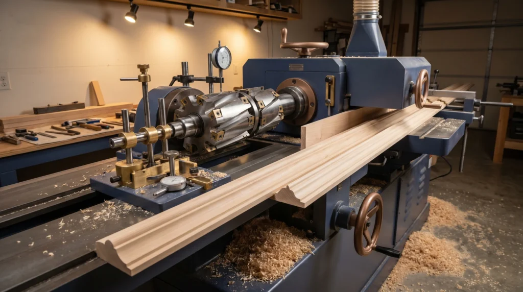
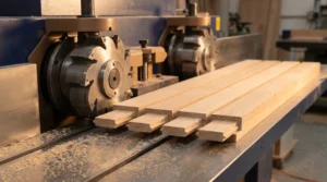
A well-set moulder is a production machine. A poorly set one is a source of headaches: snipe at the ends of boards, tear-out on figured grain, chatter marks across the face, and wasted material. The good news is that most moulder problems trace back to a handful of setup variables, and once you understand them, dialing in your machine becomes a repeatable process. This moulder setup guide covers the full sequence — from spindle loading to your first good board — and closes with a troubleshooting table for the most common issues.
Safety Before Setup
Lock out and tag out the machine before touching any spindle, tooling, or fence component. Verify all spindles are at rest. Wear cut-resistant gloves when handling knives or cutterheads. Never run a moulder without guards in place. Always follow your machine manufacturer’s safety and operating instructions, and never exceed the RPM rating of your tooling.
Know Your Spindle Order
Most four-sided moulders run in a fixed sequence: bottom, top, left, right (though this varies by machine — check your manual). Each spindle removes material in a specific sequence, and the final spindle on each face takes the finishing cut. Understanding the order matters because:
- Roughing cuts should leave enough material for the finishing spindle to clean up.
- The finishing spindle sets the final dimension and surface quality.
- Incorrect spindle sequence can cause loading on one head and starvation on another, leading to inconsistent results.
Step-by-Step Moulder Setup
- Start with clean, sharp tooling. Dull knives are the single biggest source of tear-out, burning, and poor surface finish. Inspect every knife and cutterhead before setup. If edges show any chipping, rollover, or visible wear, have them re-ground before running. CGG Schmidt can re-grind moulder knives and profile sets — it’s always worth sending dull tooling out rather than running it and ruining stock.
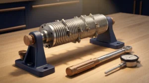
- Mount tooling on each spindle. Follow your machine manufacturer’s instructions for clamping cutterheads or knife assemblies onto each spindle. Verify that all locking hardware is tightened to spec and that tooling is seated squarely on the spindle. Spin each spindle by hand (with power locked out) and confirm there is no wobble or runout.
- Set knife projection consistently. Use a setting gauge referenced to the cutterhead body to confirm that all knives in a head are set to equal projection. Unequal projection means only the longest knife is doing the cutting — the others are along for the ride — which hammers that knife and produces a wavy surface. Take the time to check every knife in every head.
- Set each spindle to the correct cutting circle. The cutting circle of the finishing spindle on each face must correspond to your target finished dimension. Work through each spindle systematically, setting the finishing position first, then walking back to set the roughing spindles so they leave appropriate stock for the finisher.
- Set fences and guides. Infeed and outfeed fences should be set so the outfeed fence is in line with the cutting circle of the finishing bottom spindle. This is the same principle as a jointer: the outfeed table supports the newly machined surface. Misaligned fences are a primary cause of snipe.
- Adjust pressure shoes and hold-downs. Hold-downs keep the workpiece against the table and fence throughout the cut. They should apply firm, consistent downward pressure without being so tight they cause feed hesitation. Chip breakers and pressure shoes on the outfeed side of each spindle help prevent tear-out, especially on the top head. Set them just above the finished surface — typically within 1–2 mm — so they’re doing their job without impeding feed.
- Set feed speed. Feed speed directly affects chip load, surface quality, and whether the machine can keep up with your production needs. Start on the conservative side — a slower feed rate produces a finer finish but may cause burning if it’s too slow. A feed rate that’s too fast increases chip load and can cause tear-out or chatter. For most solid hardwood profiles, a moderate feed rate produces excellent results; adjust based on the material, profile complexity, and knife condition. Your machine manual will provide a recommended starting range.
- Run a test board. Before committing production stock, run a test piece of the same species and dimensions you’ll be moulding. Inspect the full length for snipe, tear-out, chatter, and dimensional accuracy. Measure the finished profile against your target. Mark any areas that need correction and work through them one variable at a time.
- Make incremental adjustments. Change one variable at a time — fence position, feed speed, hold-down pressure — so you know what each adjustment does. Changing multiple things at once makes it hard to know what fixed the problem (or made it worse).
- Confirm final setup and document it. Once you have a good board, document your setup: spindle heights, fence positions, feed speed, hold-down settings. Good setup records let you return to a proven configuration for repeat runs without starting from scratch.
Troubleshooting Common Moulder Problems
| Problem | Likely Cause | Fix |
|---|---|---|
| Snipe at board ends | Outfeed fence not aligned to cutting circle | Align outfeed fence to finishing spindle cutting circle |
| Snipe at board ends | Hold-downs releasing before board clears head | Extend hold-down coverage; check pressure shoe length |
| Tear-out on top face | Dull top knives | Re-grind or replace top head knives |
| Tear-out on top face | Feed speed too high for material | Reduce feed speed; increase pressure shoe engagement |
| Tear-out on figured/interlocked grain | Cutting against grain direction | Reverse board direction if possible; reduce depth of cut |
| Chatter marks | Loose tooling or worn spindle bearings | Re-torque all tooling; inspect spindle bearing play |
| Chatter marks | Unequal knife projection | Re-set knife projection equally across all knives in head |
| Burning on face | Feed speed too slow | Increase feed speed incrementally |
| Burning on face | Dull knives | Re-grind before running further |
| Dimension inconsistency | Hold-downs too loose | Increase hold-down pressure; check for worn feed rolls |
| Profile not matching target | Incorrect cutting circle height | Re-set finishing spindle to correct height; re-run test board |
A Note on Profile Knives
CGG Schmidt maintains a library of more than 170 standard profiles and can grind custom moulder knives from a sketch, a wood sample, or a DXF file. If you’re transitioning to a new profile or need replacement knives for an existing run, getting knives that are properly ground to a matched set saves significant setup time.
When you’re ready to optimize your moulder setup or need sharp tooling to back it up, reach out to Charles G.G. Schmidt & Co. at 1-800-SCHMIDT or sales@cggschmidt.com. We’ve been helping shops like yours run better since 1926.